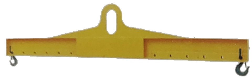
Lifting Beams & Special Lifting Devices
Adjustable Multi-Point Balance Beams (I-Beam / Spreader Beams)
High-strength box or section-steel welded structure with multiple equidistant lifting-eye positions; the spread is set to the load centre of gravity, eliminating horizontal forces from angled lifts.
Key Features
- Beam body in high-quality low-carbon alloy structural steel, box or streamlined section; low dead weight with high bending stiffness
- Multiple equidistant lifting-eye positions; the spread is set to the load centre of gravity, eliminating horizontal forces from angled lifts
- Supplied with pin shafts and eye-type swivel hooks; can also be combined with two-leg or four-leg chain slings
- Standard beams cover 2 – 40 t with 1 – 12 m effective length; higher capacities and spans are designed to order
- Shot-blasted and painted; colour and private labelling to customer requirement
- Batch-wise outgoing inspection; test report and certificate supplied with each delivery, heat / batch number traceable
Technical Data (reference values; refer to the specification sheet)
| Working Load Limit (WLL) | Standard beams 2 – 40 t (series 370 / 371 / 377); designed to order up to 200 t |
|---|---|
| Span / Effective Length | 1 – 12 m as standard, extendable to 16 m to suit the load size |
| Material | High-quality low-carbon alloy structural steel (box / streamlined beam body) |
| Construction | Single straight beam / spreader beam with multiple equidistant lifting eyes |
| Matching Slings | Pin shafts, eye-type swivel hooks, two-leg or four-leg chain slings |
| Applicable Standards | Designed and manufactured to industry standards and drawings |
| Inspection & Traceability | Batch-wise outgoing inspection; test report and certificate supplied with each delivery; heat / batch number traceable |
| Custom Manufacturing | WLL, span, number of lifting points and eye pitch can all be non-standard, to drawings |
Full Specification Table
Scroll horizontally to view all columns
Table 1 · HLA Spreader Beam Series Specifications (Code 370)
HLA Spreader Beam (Code 370)11 sizes,2 – 40 t。High-quality low-carbon alloy structural steel, box or streamlined section; supplied with pin shafts and eye-type swivel hooks, hook position adjustable to the load size.
| WLL (t) | Adjustable Range (m) | Effective Length L1 (m) | A (mm) | B (mm) | C (mm) | L (mm) | H (mm) |
|---|---|---|---|---|---|---|---|
| 2 | 2–3 | 3 | 80 | 150 | 570 | 3184 | 180 |
| 3.2 | 3–5 | 5 | 100 | 220 | 828 | 5200 | 300 |
| 5 | 3–5 | 5 | 100 | 220 | 935 | 5300 | 300 |
| 8 | 4–6 | 6 | 160 | 360 | 1140 | 6312 | 340 |
| 10 | 4–6 | 6 | 160 | 360 | 1140 | 6320 | 340 |
| 12.5 | 4–6 | 6 | 180 | 400 | 1320 | 8320 | 370 |
| 16 | 6–8 | 8 | 180 | 430 | 1370 | 8320 | 450 |
| 20 | 6–8 | 8 | 180 | 430 | 1485 | 8360 | 450 |
| 25 | 6–8 | 8 | 200 | 500 | 1755 | 8500 | 530 |
| 32 | 8–10 | 10 | 220 | 600 | 2135 | 10640 | 650 |
| 40 | 8–10 | 10 | 220 | 600 | 2165 | 10640 | 650 |
A / B / C / L / H are the overall beam dimensions; verify lifting-point spread, lift angle and load centre of gravity together to avoid eccentric loading.
Table 2 · HLB Spreader Beam with Chain Slings Specifications (Code 371)
HLB Spreader Beam with Chain Slings (Code 371)11 sizes,2 – 40 T。Box or streamlined section, supplied with pin shafts and two-leg chain slings.
| WLL (t) | Adjustable Range (m) | Effective Length L1 (m) | Main Eye Dimensions D / E / F (mm) | Overall Dimensions A×B×C (mm) |
|---|---|---|---|---|
| 2 | 1–3 | 3 | 80 / 20 / 150 | 3180 × 160 × 1800 |
| 3.2 | 3–5 | 5 | 90 / 24 / 160 | 5200 × 210 × 2100 |
| 5 | 3–5 | 5 | 100 / 28 / 190 | 5300 × 240 × 2400 |
| 8 | 6–8 | 8 | 110 / 32 / 200 | 8350 × 250 × 3800 |
| 10 | 6–8 | 8 | 120 / 34 / 230 | 8350 × 280 × 3850 |
| 12.5 | 6–8 | 8 | 135 / 38 / 250 | 8350 × 280 × 3900 |
| 16 | 6–8 | 8 | 140 / 42 / 270 | 8350 × 300 × 4050 |
| 20 | 6–8 | 8 | 160 / 46 / 310 | 8400 × 300 × 4150 |
| 25 | 6–8 | 8 | 180 / 52 / 330 | 8460 × 380 × 4300 |
| 32 | 6–8 | 8 | 180 / 56 / 330 | 10500 × 480 × 4550 |
| 40 | 6–10 | 10 | 220 / 69 / 396 | 10500 × 480 × 4650 |
D / E / F are the main eye dimensions; chain slings are selected to match the WLL and chain grade.
Related Products in This Series
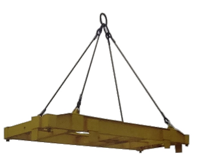
H-Type Spatial Beam Systems, Frame Beams & Container SpreadersH-Type Spatial Beam Systems, Frame Beams & Container Spreaders
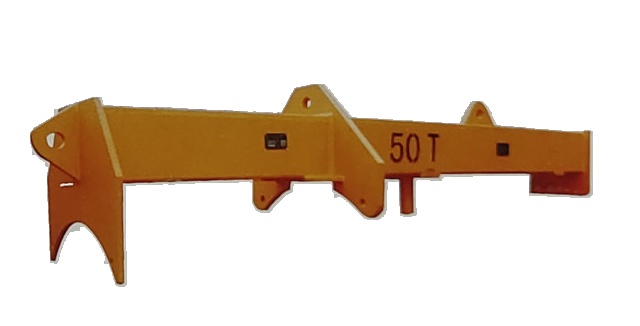
Turbine Rotor Lifting Beams & Railway Rescue BeamsTurbine Rotor Lifting Beams & Railway Rescue Beams
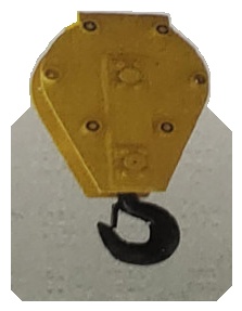
Heavy-Duty Crane Hook Blocks & Vacuum LiftersHeavy-Duty Crane Hook Blocks & Vacuum Lifters